Quick Links
|
Key Features
Applications

|
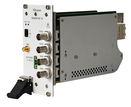

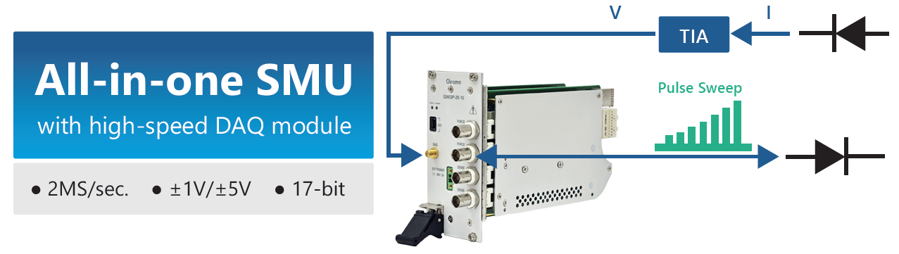
Chroma's 52403P is a PXI Express Short Pulse SMU (Source/Measure Unit) designed for fast, precise and reliable sourcing and measurement of thermo-sensitive devices such as high-power laser diodes (LD). Integrating a high-speed pulser, a highprecision SMU and a DAQ module into a single PXIe SMU, the 52403P can measure both the LIV and the low-level leakage current of high-power LDs. Chroma's Short Pulse SMU 52403P thus provides customers with an all-inone solution for comprehensive LD testing.
Featuring an excellent pulser with high slew rates and high output current, the 52403P can output either 10A/10uS pulses or 1A/5uS pulses. As inductance substantially affects pulse current rise/fall times, the 52403P Short Pulse SMU allows up to 3uH inductance between the test lead and the DUT while still providing 10A/10uS or 1A/5uS pulse curves.
The 52403P's SMU module is equipped with 16 selectable control bandwidths to ensure fast and stable output that can meet different DUT impedance requirements and avoid oscillation. Multiple current measurement ranges with 18-bit DAC and 18-bit ADC provide high resolution and accuracy with a sampling rate of up to 100 kS/s.
With its built-in 2 MS/s DAQ (Data Acquisition), Chroma 52403P can measure the voltage signal of high-speed photodiodes through a TIA (Transimpedance Amplifier) using its own SMU, which simplifies test system integration and cuts down on development time.
A versatile soft front panel and C/C#/LabVIEW/LabWindows APIs are provided for rapid test development and deployment. The back connector is compatible with both PXIe and hybrid chassis slots. All of these features enable easy integration to PXIe or PXIhybrid systems designed for a wide range of applications.
The 52403P has a patented hardware sequence engine that has deterministic timing to control SMU output. The sequencer's on-board memory can store up to 8192 sequencer commands and a total of 8M measurement samples.
Short Pulse Current Curve
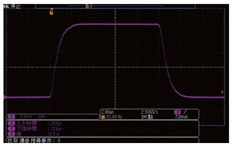
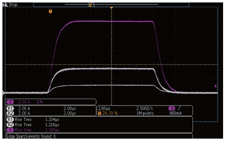
Excellent high-slew-rate design allows Chroma's Short Pulse SMU 52403P to output 10A/10uS pulses and 1A /5uS pulses that prevent the laser diode from self-heating. In Figure 1, we see the pulse waveform of a 10A/10uS current along a 3m cable. Figure 2 shows only minor differences in rise times between 10A/3.5A/1A 10uS pulse curves when using a 3m cable. Lastly, we see in Figure 3 how different cable lengths produce nearly identical 10A/10uS pulse curves, demonstrating that the 52403P can output highly precise pulse curves with minimal impact from output current and cable length.
 |
 |
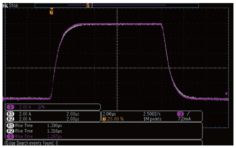 |
| Figure 1: 10A/10uA pulse curve |
Figure 2: Pulse curve with 10A/3.5A/1A output |
Figure 3: Pulse curve with 3M/2M/1M cables |
Two-In-One: Bidirectional DC Power Supply and Load
The LIV (Light-Current-Voltage) test is an important measurement used to collect data about the operating characteristics, slope efficiency and threshold current of devices such as laser diodes. Another important function of the LIV test is to identify "kinks" in the output curve. Unlike other SMUs, the 52403P can output uS-level pulsed sweeps to the laser diode (LD). The LD emits light to the photo detector (PD), which then generates current that is converted into voltage by the TIA. the 52403P's built-in DAQ then collects the voltage signal and generates an LIV curve by calculating the Sweep I/V data and L data, as shown in Figure 4.
Quadrant Diagram
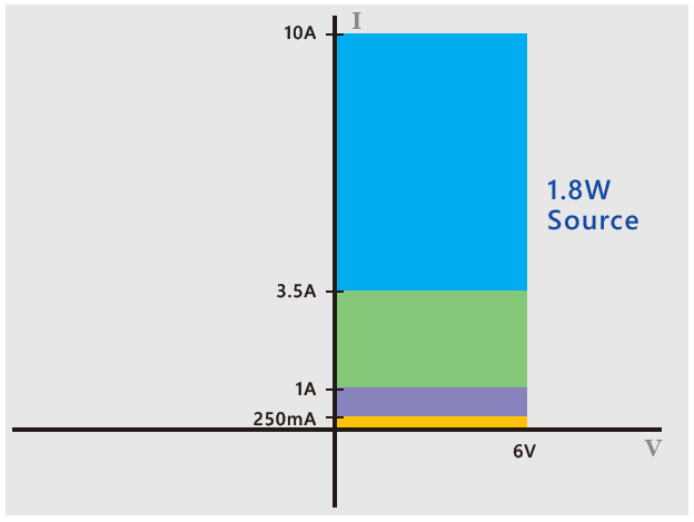
The Short Pulse SMU 52403P come equipped with a pulser module and an SMU module. The pulser module provides quadrant-1 output of 1.8W (Figure 5), and the SMU module provides 4-quadrant output with 25W output as a source and 10W as a load (Figure 6).
 |
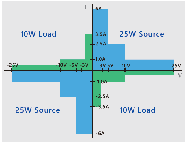 |
| Figure 5: Quadrant diagram of the pulser module | Figure 6: Quadrant diagram of the SMU mod |
Versatile Soft Front Panel
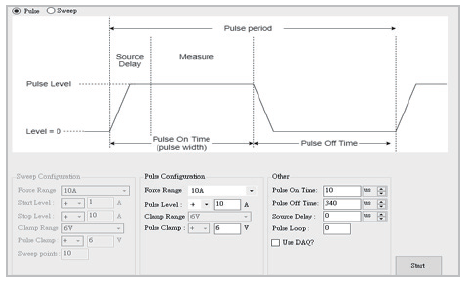
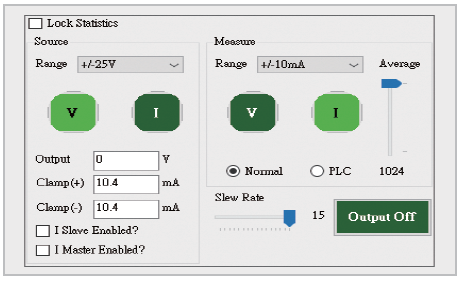
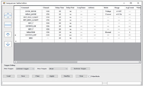
Chroma provides a user-friendly soft front panel for a range of applications. The Pulser Module Soft Front Panel (Figure 7) enables customers to easily edit pulse waveforms by simply adjusting a few pulse parameters. The SMU Module Soft Front Panel (Figure 8) allows customers to input major setup parameters, such as range, clamp values, aperture time and loop bandwidth for high-precision test and measurement. The Hardware Sequencer Soft Front Panel (Figure 9) allows latency-free control and measurement without requiring any PC interaction during execution. Once the instrument receives the start trigger, it will execute the step commands in the sequencer table line-by-line or as defined by the trigger.
 |
 |
 |
| Figure 7: Pulser module software front panel |
Figure 8: SMU module software front panel |
Figure 9: Hardware sequencer software front panel |
SMU Module Guarding For Low Current Application
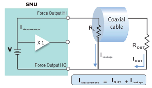
Guarding is an important technique for very-low current measurements that reduces errors caused by leakage current and decreases settling time (Figure 10). This is achieved by keeping the potential of the guard connector at the same potential as the force conductor, so as to prevent current from flowing between the force and guard conductors. Guarding also eliminates the cable capacitance between the SMU and DUT (Figure 11) and significantly reduces the RC time constant. The SMU module features two ±guard wires, resulting in faster and more accurate measurements.
 |
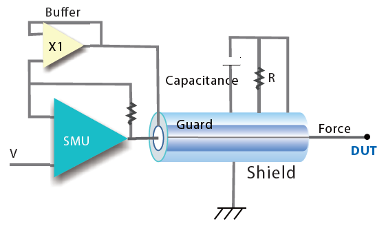 |
| Figure 10: Leakage current flowing through the cable's insulation resistance | Figure 11: Guard connection - cable capacitance is eliminated with a triaxial cable |
SMU Module Control Bandwidth
The SMU module is designed to provide high-speed output voltage and current for optimal responsivity and reduced time of test. The impedance of the DUT, fixture, or cabling may cause loop instability in voltage or current source mode, which in turn can cause saturation, oscillation, or even damage to the DUT. To prevent this, the SMU module provides 16 user-selectable control bandwidths, eliminating the need for external capacitors or inductors placed near the DUT. This results in faster output rise time, reduced voltage ripple and noise, and reduced transient response (Figure 12). The control bandwidth can be modified via software to maximize test flexibility and minimize downtime when changing DUTs.
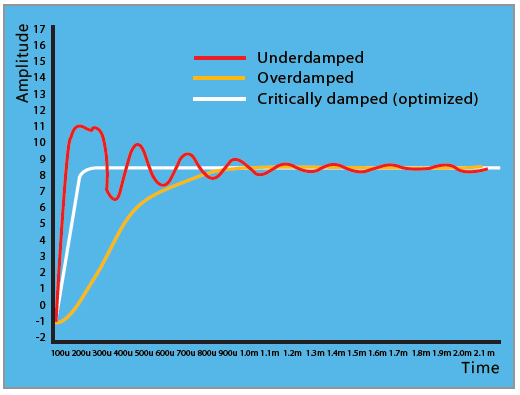 |
| Figure 12: SMU output waveform under bandwidth control |
Home | Solutions | Support | Press Center | About Chroma | Contact
Copyright © Chroma ATE, Inc. All Rights Reserved.